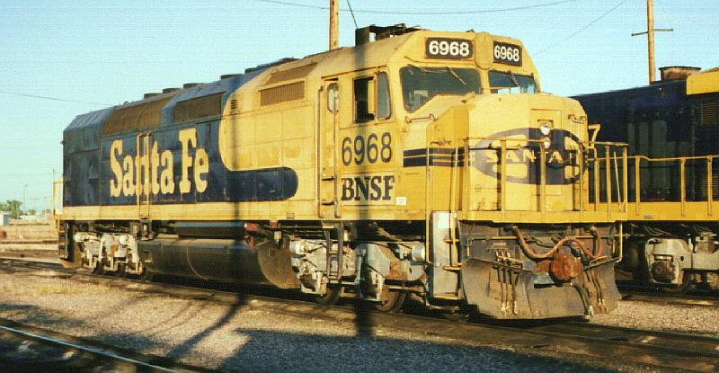
Cowl Units On November 19, 2000 I had the BNSF 6969 as my 2nd unit. It is a former Santa Fe SDP40F cowl unit which originally belonged to Amtrak. For use in freight service ATSF made some modifictions to these units such as cutting notches in the corners of the wide nose for steps and installing a front catwalk and nose door. The 6969 I had trailing that night was still painted in ATSF's blue & yellow freight scheme but had been renumbered and had BNSF stickers applied. That trip was made entirely at night and I never got a chance to get a photo of the 6969's exterior. However I did take a slide of its sister unit, the 6968 shown here, at the Laurel roundhouse in July of 1998.
While I was unable to get an exterior shot of the 6969 I was able to go back into its engine room while stopped in the siding at Benteen.
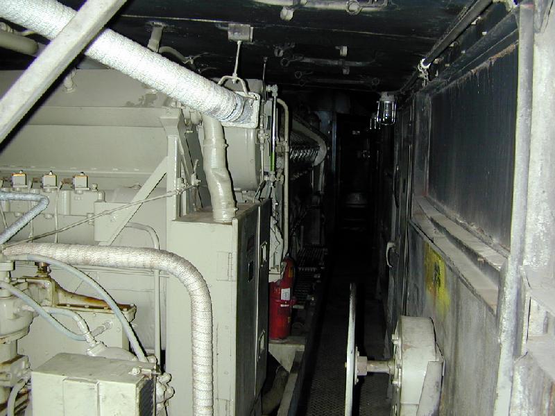
Ahh... it has been a while since I've walked INTO an engine room. The dim light. The noise. The heat. The smell of hot oil and fuel. I took some photos of it and the cab.The first picture is looking up along the rightside of the engineroom towards the door to the cab. The lights are burned out, an FRA defect, so it is very dark up the walkway. The loco's handbrake wheel is along the righthand wall. Up the walkway a few steps is a red fire extinguisher mentioned later. In the lower left of the picture is the air compressor.
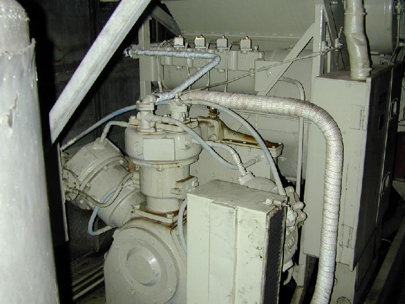
Here is a better picture of the 3 cylinder aircompressor. It is water cooled and shaft driven from the engine. The compressors run all the time the engine is running. To stop the compressor from pumping air after the main reservoirs are at the proper pressure the compressor's valves are held open by control air. The compressors have their own oil system. The small boxes above the compressor are the thermostat switches that turn each of the 3 radiator fans on at a different temperature and the radiator shutter control switch. The big thing along the left edge of the picture is a concrete ballast weight.
For the next photo I've walked forward up to where the red fire extinguisher is in a previous shot. We are still looking up the walkway towards the cab.
Our 3600 HP BN F45s had 20 cylinder engines but this 3000 HP SDP40F only has 16 cylinders. You can tell that it has a shorter engine as soon as you step into the engine room account of all the extra room at the back of the unit. You can also tell a 20 cylinder from a 16 cylinder by counting the cylinder drain cocks or the hand hole covers. The cylinder drain cocks are those "pegs" sticking out from the side of the block just below the valve train cover latches. These cocks are supposed to be opened before cranking an engine that has been sitting dead for some time. Water can leak by seals and get into the cylinders as an engine cools. If you crank an engine with water in the cylinders the piston will push the water up to the head and a hydraulic lock will occur. That can do major damage to the engine itself. By opening these cocks the water has a way to squirt out of the cylinder thus preventing damage. You can count 8 cocks on this side. There are an equal number on the other side of the block. Thus this is a 16 cylinder engine. The round covers below are hand hole covers that give access to the inside of the engine itself. The top row are for the airbox area and the bottom row are for the crankcase. Again there are 8 of each on each side of the block.
In the very bottom left of the photo you can see two silver buttons. One is the Low Water button and the other is the Crankcase Over pressure button. If either one trips its button will pop out a little bit revealing a red ring around it. To reset it you simply push it back in to latch. When these buttons trip they in turn trip the Low Oil shut down on the governor which stops the engine. So you also have to reset the Low Oil button which is located on the backside of the governor itself. Because of the danger of a crankcase explosion, the rules prohibit crewman resetting the Crankcase Over Pressure if it trips.
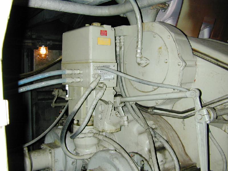
While standing at the same location as above I turned to the left and took the next picture of the accessory end of the unit's EMD 645 prime mover.
It shows the governor and the linkages to the layshafts which control the fuel injector settings. The vertical lever at the lower righthand corner of the photo is the layshaft handle. By pushing on this lever you can manually rev up the diesel engine. It is sometimes necessary to push in a little bit on it when starting the engine to give it a bit more fuel while cranking.
The governors have their own separate oil supply. You can see a small oil sight glass mounted on the governor that is used to check the level of this oil.
The two hoses coming from the governor that run towards the left edge of the photo are the oil lines to the load regulator. The governor controls the electrical output of the main traction alternator by hydraulically controlling the load regulator. (Shown later).
The other hoses coming from the governor go to engine protective devices such as Low Water shut down, crankcase Over Pressure shut down, and Low Oil pressure shut down.
The two circular devices below the governor on either side are the engine's water pumps.
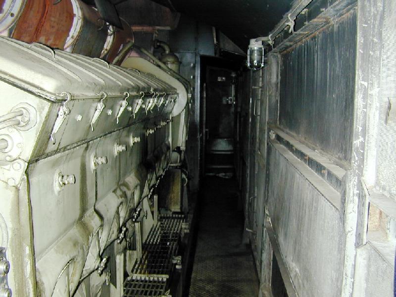
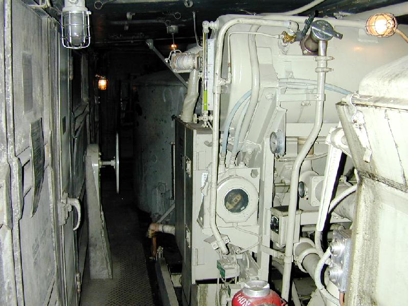
Taking a few more steps forward up the walkway and then turning around to look back in the direction from which we came you see the view of the next photo.
You can see the same handbrake wheel as before. In the distance in the darkness you can see the large verticle cylinder of concrete that is used as weight to ballast the locomotive. When these units were in passenger service for Amtrak they would have had a steam boiler in the dark rear section seen in this view.
The horizontal cylindrical object up at eye level is the water expansion tank for the diesel engine's cooling water. You can see a vertical water sight glass tube mounted on the end of the tank. It is about 1/3 full of green water. The water is green because it is treated with corrosion inhibitors. The water in some units is pink. The silver cap up on the side of the tank is the water fill.
Below the water sight glass, the circular thing with the dark window in it is the load regulator. This is a large potentiometer. (rheostat). The lighter colored thing at a 45 degree angle, inside behind the window, is the wiper arm of the potentiometer. The position of this wiper arm is hydraulically controlled by the governor to regulate the electrical output of the main traction alternator.
Above and to the right of the load regulator is the engine oil pressure guage. Below and to the right of that is the engine water temperature guage. Below and to the left of that is the engine start switch. Near the lower righthand corner of the photo are the two silver colored Low Water and Crankcase Over Pressure buttons mentioned in another photo.
Backing up about 20 feet and looking the same direction as the previous photo we get this view along the engine. The "rusty barrels" on top the engine is the exhaust manifold.
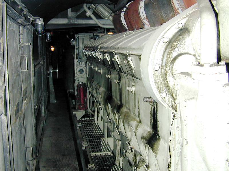
In the above photo if I were to turn 90 degrees to my right I would see the turbocharger. Below that would be the large main traction alternator. Unfortunately you are too close to them to get any meaningful pictures.
About ten feet or so behind my location in the photo above is the door into the cab. Open it and climb in on page two.

